Design for CNC Machining: 13 Rules for Better, Lower-Cost Parts
Practical DFM rules for CNC machined parts - internal radii, wall thickness, hole and thread depth, tolerances and finishes - that cut cost and lead time before you ever request a quote.

Most of a machined part's cost is decided long before a single chip is cut. The geometry you draw determines how many setups the part needs, which cutting tools can reach each feature, how slowly the machine has to run, and how much hand-finishing the shop must add at the end. Design for manufacturing (DFM) is the discipline of shaping a part so it is easy to hold, easy to cut, and easy to inspect — without compromising the function it has to perform.
This guide collects the practical rules our engineers apply most often when reviewing CNC machining drawings. None of them require exotic knowledge; they simply reflect how a milling cutter or lathe tool physically interacts with metal and plastic. Follow them and your parts will quote lower, ship faster, and pass inspection more reliably.
Why DFM Matters More for CNC Than You Think
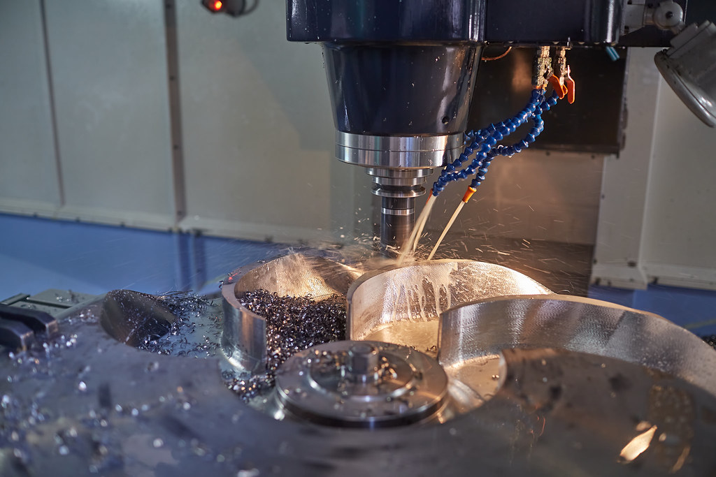
A CNC machine removes material with rotating tools that have a finite diameter, a finite reach, and a finite stiffness. Every feature you design is ultimately produced by one of those tools moving through the stock. When a feature fights the tool — a corner too sharp for any end mill to reach, a pocket too deep for the tool to stay rigid, a wall too thin to resist cutting forces — the shop has three options: run slower, switch to a smaller or custom tool, or add an extra operation. All three add cost and lead time.
The good news is that small design changes usually preserve function while dramatically improving manufacturability. A corner radius increased by half a millimetre, a tolerance opened from ±0.02 mm to ±0.1 mm where it does not matter, or a pocket made 2 mm shallower can each shave real money from a part. The rules below are where that money lives.
1. Maximize Internal Corner Radii
End mills are round, so they cannot cut a perfectly sharp internal corner — there is always a radius equal to the tool radius. Specifying a tiny internal radius forces the shop to use a tiny tool, which must run slowly and deflects easily. As a rule, make internal vertical radii as large as the design allows, and keep them consistent so one tool can cut them all. A radius of at least one-third of the cavity depth lets the shop use a properly sized, rigid tool. If a mating part truly needs a sharp corner, add a small relief or "dog-bone" undercut rather than demanding a zero radius.
2. Limit Pocket and Cavity Depth
Tool stiffness falls with the cube of its length, so deep pockets force slow, light cuts to avoid chatter and tool breakage. Keep cavity depth within about four times the tool diameter for routine work; deeper than that and cost climbs quickly. If you need a deep, narrow pocket, ask whether it can be opened up, split across a part line, or reached from both sides.
3. Keep Walls Thick Enough
Thin walls vibrate under cutting forces, which ruins finish and accuracy and can shatter brittle materials. For metals, keep walls at or above roughly 0.8 mm; for plastics, 1.5 mm is a safer floor because they are less rigid and dissipate heat poorly. Where a thin wall is unavoidable, support it with ribs or leave extra stock for a light finishing pass. Our companion wall thickness design guide covers minimums by process and material in detail.
4. Design Standard, Reasonable Holes
Holes are drilled or interpolated, and standard drill sizes are far cheaper than odd diameters that require boring or custom tooling. Whenever tolerance allows, specify hole diameters that match common drill bits. Keep hole depth within about four to six times the diameter for standard drills; deeper holes need special tooling and peck cycles. Avoid holes that break into a cavity at a steep angle, which can deflect the drill and create burrs that are hard to remove.
5. Tap Threads to a Sensible Depth
There is rarely a functional benefit to threading a hole deeper than about 1.5 to 2 times its diameter — the first few threads carry almost all the load. Over-deep tapped holes increase the risk of tap breakage in the blind end and add cycle time. Use standard thread sizes, allow room for thread relief, and avoid tapping right up to the bottom of a blind hole. See our guide to threads in machined parts for standards and design rules.
6. Avoid Tall, Thin Features
Tall bosses, thin fins, and slender pins behave like tiny diving boards under the side load of a cutter. As a guideline, keep the height-to-thickness ratio of standing features below about 4:1. If a part needs a tall feature, consider adding a fillet at its base for stiffness, or splitting the design so the feature is machined separately and assembled.
7. Use Standard Tolerances — Tighten Only What Matters
A general tolerance such as ISO 2768 medium is essentially free because the machine holds it naturally. Every callout tighter than that adds inspection steps, slower finishing passes, and scrap risk, so reserve tight tolerances for the few features that actually mate or seal. Applying ±0.01 mm across an entire part — when only one bore needs it — can multiply cost for no functional gain. Thinking in terms of function also helps control tolerance stack-up across an assembly, and pairs naturally with sound GD&T practice.
8. Minimize the Number of Setups
Each time a part must be re-fixtured to reach a new face, the shop adds handling time and a small alignment error between setups. Parts that can be machined from one or two sides are cheaper and more accurate than parts requiring five faces. Where possible, group features onto fewer faces, provide a flat and a square edge for work-holding, and avoid features that demand awkward angular setups unless 5-axis machining is genuinely warranted. Our overview of 5-axis CNC machining explains when the extra axes pay for themselves.
9. Avoid Undercuts, or Design Them for Standard Tools
Internal undercuts and grooves cannot be reached by a standard end mill and require specialty cutters such as T-slot or lollipop tools — or a different process entirely. If an undercut is essential (for an O-ring groove or a retaining ring, for example), dimension it to suit a standard cutter geometry rather than an arbitrary shape, and put it on an accessible external face wherever you can.
10. Engrave and Emboss Text Wisely
Raised (embossed) text forces the machine to clear all the surrounding material, which is slow; recessed (engraved) text only cuts the characters themselves and is far cheaper. Keep text to a reasonable size, use a sans-serif font, and prefer engraving for part numbers and logos. For high volumes or very fine marking, laser engraving as a secondary operation is usually faster and crisper than milling.
11. Specify the Right Surface Finish
As-machined finish is included in the base price; anything beyond it — bead blasting, anodizing, plating, polishing — is an added operation with its own cost and lead time. Specify a finer finish only on surfaces that need it for sealing, sliding, or appearance, and leave non-cosmetic faces as-machined. Our guide to surface finishes explains how to choose and call out the right finish.
12. Choose a Machinable Material
Material choice swings both cost and lead time. Free-machining alloys such as 6061 aluminium or 303 stainless cut quickly and cleanly; harder or gummier materials such as titanium or certain stainless grades cut slowly and wear tooling faster. If two materials both satisfy the design, the more machinable one will usually be cheaper. Compare common options in our guides to aluminium alloys for machining and stainless steel grades.
13. Send a Complete, Unambiguous Drawing
Even a perfectly designed model quotes slowly if the shop has to guess at critical dimensions, material, finish, or quantity. Provide a 3D model for geometry and a 2D drawing for the few controlled dimensions, datums, tolerances, threads, and finish callouts. Clear documentation removes back-and-forth and protects you from costly misinterpretation — the same discipline we cover in writing an effective RFQ.
Quick-Reference DFM Guidelines
| Feature | Rule of Thumb | Why It Helps |
|---|---|---|
| Internal corner radius | ≥ 1/3 of cavity depth; keep consistent | Allows a rigid, standard end mill |
| Pocket depth | ≤ ~4× tool diameter | Limits tool deflection and chatter |
| Minimum wall (metal) | ≥ 0.8 mm | Resists vibration and distortion |
| Minimum wall (plastic) | ≥ 1.5 mm | Compensates for low rigidity |
| Hole depth | ≤ ~4–6× diameter (standard drill) | Avoids special deep-hole tooling |
| Thread depth | ~1.5–2× diameter | Full strength without tap breakage risk |
| Standing feature height | ≤ ~4× its thickness | Prevents flexing under cutting load |
| General tolerance | ISO 2768-m unless function demands tighter | Tight callouts only where needed |
Designing With the Process in Mind
The thread running through every rule above is empathy for the tool. A machinist cannot cut what a tool cannot reach, hold rigidly, or measure repeatably. When you picture the cutter moving through your part as you design it, most DFM problems solve themselves: corners get radii, pockets get shallower, tolerances relax where they can, and the part becomes something a shop can make quickly and consistently. Spending time on cost reduction at the design stage pays back many times over, as our guide to reducing CNC machining costs explores in depth.
If you would like a second set of eyes before you commit a design to production, MechPart Pro's engineers provide free design-for-manufacturability feedback with every quote. Upload your model and drawing and we will flag thin walls, hard-to-reach features, tight tolerances, and material choices that drive cost — then suggest changes that keep your part's function while lowering its price and lead time. It is the fastest path to a part that is right the first time.
Related capabilities
Have a part to make?
Upload your CAD for a detailed quote and free DFM feedback within 24 hours.