Wall Thickness Design Guide: CNC, Injection Molding, Casting & 3D Printing
Minimum and recommended wall thickness by process and material - CNC machining, injection molding, die casting, sheet metal and 3D printing - plus how to avoid warp, sink and breakage.

Wall thickness is one of the few design parameters that touches every manufacturing process at once. Make a wall too thin and the part vibrates under a cutting tool, tears during sheet bending, fails to fill in a mold, or cracks coming off a print bed. Make it too thick and you waste material, trap heat, and — in molded and cast parts — invite sink marks, porosity, and warpage. Getting wall thickness right is therefore one of the highest-leverage decisions an engineer makes.
This guide gathers practical wall-thickness guidance across the processes we run most often — CNC machining, injection molding, die casting, sheet metal, and 3D printing — and explains the failure modes each process is trying to avoid. Treat the numbers as well-tested starting points; the right value for your part always depends on its material, size, and function.
The Golden Rule: Keep Walls Uniform
Before any specific number, one principle outranks the rest: keep wall thickness as uniform as possible. This matters most in processes where material solidifies from a liquid — injection molding, die casting, and to a degree metal 3D printing — because thick and thin regions cool at different rates. The thicker section stays molten longer, shrinks more as it finally cools, and pulls the surface inward, leaving a visible sink mark or an internal void. Uniform walls cool evenly, so the part stays dimensionally stable and free of those defects.
When a design genuinely needs a thick region — for stiffness or a bearing surface — the preferred fix is to "core it out": hollow the thick zone and replace its stiffness with ribs of normal wall thickness. This keeps the effective wall uniform while preserving strength, and it saves material and cycle time at the same time.
CNC Machining
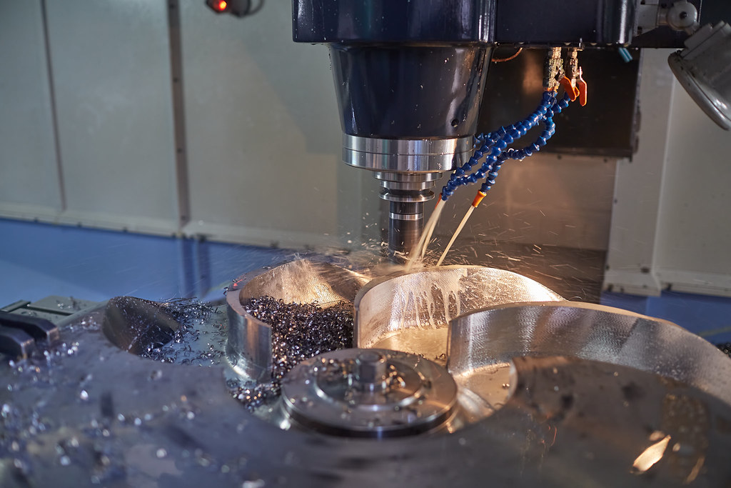
In machining, wall thickness is governed by rigidity rather than flow. A thin wall flexes away from the cutter and chatters, which spoils surface finish and dimensional accuracy; in brittle materials it can crack outright. For metals, a minimum wall of about 0.8 mm is a safe floor for routine work, and 0.5 mm is achievable only with light finishing cuts, careful work-holding, and a cost premium. For plastics, raise the minimum to about 1.5 mm, because polymers are far less stiff and shed heat poorly, so they deflect and soften under the tool.
If a thin wall is unavoidable, you can support it with a backing rib, machine it in stages leaving stock for a final spring pass, or orient the feature so cutting forces push into solid material rather than across the thin section. These choices interact with the broader rules in our design for CNC machining guide.
Injection Molding
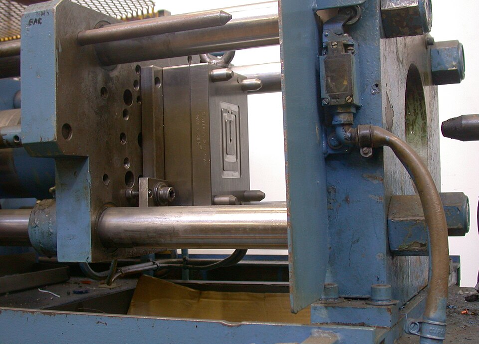
Molding is where wall thickness rules are strictest, because molten plastic must flow through the entire cavity before it freezes. Walls that are too thin cause short shots (incomplete fill); walls that are too thick cause long cooling times, sink, and warp. Most thermoplastics mold best in a band of roughly 1.0 to 4.0 mm, with the practical sweet spot for many parts between 2 and 3 mm. The ideal value is resin-specific, as the table below shows.
Three companion rules keep molded walls healthy: make ribs about 50–60% of the adjoining wall thickness so they stiffen without sinking; add a draft angle of a degree or more so the part releases cleanly; and blend thickness transitions gradually rather than stepping abruptly. Our injection molding design guide covers gates, ribs, and defect fixes in more depth.
Die Casting and Sand Casting
Cast metals follow the same solidification logic as molded plastics, with their own numbers. Die casting fills a steel die under high pressure and supports thin walls well — aluminium die castings commonly run 1.5 to 3 mm, zinc even thinner. Sand casting is far more forgiving of geometry but needs thicker walls — typically 3 to 5 mm or more — because the sand mold and slower cooling cannot reliably fill thin sections. As with molding, uniform walls and generous fillets at junctions prevent shrinkage porosity and hot tears. The trade-offs between casting routes are compared in our guide to investment casting vs. sand casting.
Sheet Metal
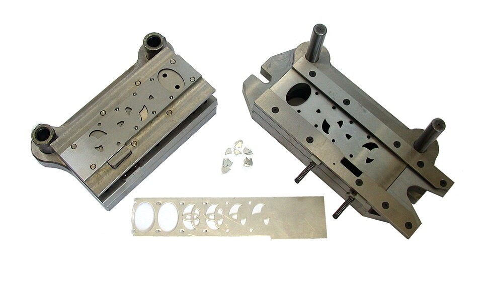
Sheet metal is a special case: wall thickness is simply the gauge of the stock, and it is uniform by definition. What thickness controls here is the geometry of features formed in that sheet. The minimum internal bend radius should be at least equal to the material thickness to avoid cracking on the outside of the bend. Holes and slots should sit at least 2–3 thicknesses away from a bend, or they distort as the metal stretches. And the smallest features — tabs, holes, notches — generally cannot be smaller than the sheet thickness itself. Our sheet metal fabrication guide details these rules and common gauges.
3D Printing
Additive processes build walls layer by layer, so the minimum wall depends on the technology and the nozzle, laser, or jet resolution. Fused deposition (FDM) needs walls that are a multiple of the extrusion width — typically 0.8 to 1.2 mm — so the perimeters bond. Powder-bed processes such as SLS and Multi Jet Fusion hold detail well and can run walls around 0.7 to 1.0 mm, while resin SLA can go finer still. Metal powder-bed printing (DMLS/SLM) usually wants at least 0.4 to 0.5 mm for self-supporting, fully dense walls. Very tall thin walls in any process risk warping or detaching, so add ribs or gussets for stability. See our overview of metal 3D printing for process specifics.
Minimum Wall Thickness by Process
| Process / Material | Typical Minimum Wall | Recommended Range | Main Failure Mode if Too Thin |
|---|---|---|---|
| CNC machining — metal | 0.8 mm | 1.0–3.0 mm | Chatter, distortion |
| CNC machining — plastic | 1.5 mm | 2.0–4.0 mm | Deflection, softening |
| Injection molding | 1.0 mm | 2.0–3.0 mm | Short shot (incomplete fill) |
| Aluminium die casting | 1.5 mm | 2.0–3.0 mm | Misrun, cold shut |
| Sand casting | 3.0 mm | 4.0–6.0 mm | Incomplete fill, shrinkage |
| FDM 3D printing | 0.8 mm | 1.2–2.0 mm | Weak, unbonded perimeters |
| SLS / MJF 3D printing | 0.7 mm | 1.0–2.0 mm | Warping, breakage |
| Metal 3D printing (DMLS) | 0.4 mm | 0.6–1.0 mm | Porosity, detachment |
How to Handle Sections That Must Be Thick
When function demands a heavy section — a mounting boss, a gear hub, a sealing land — resist the urge to leave it solid in a molded or cast part. Instead:
- Core out the mass. Hollow the interior and leave a uniform wall around it, so the part cools evenly.
- Add ribs instead of bulk. A grid of thin ribs delivers most of the stiffness of a solid block at a fraction of the wall thickness.
- Blend transitions. Where thickness must change, taper over a distance of at least three times the wall rather than stepping abruptly, so stress and cooling stay gradual.
- Use fillets at junctions. Sharp inside corners concentrate stress and create local thick spots; a fillet smooths both.
Designing for the Whole Part
Wall thickness rarely acts alone — it interacts with ribs, bosses, draft, tolerances, and material choice. The most reliable approach is to settle on a uniform nominal wall early, size every other feature relative to it, and reserve deviations for places where function truly requires them. Doing so heads off the most common and expensive defects in molded, cast, machined, and printed parts alike.
If you are unsure whether your walls suit the process you have in mind, MechPart Pro's engineers will review your model as part of our free design-for-manufacturability feedback. We will flag thin sections that may fail, thick sections that may sink or warp, and transitions that invite stress — across CNC machining, injection molding, casting, sheet metal, and 3D printing — so your first parts come out right. Upload a model to get a quote and that feedback together.
Related capabilities
Have a part to make?
Upload your CAD for a detailed quote and free DFM feedback within 24 hours.