Threads in Machined Parts: Types, Standards & Design
A practical guide to thread standards (metric ISO, UNC/UNF, NPT/BSPP), how threads are produced, design rules for fit and depth, and pitfalls to avoid.

Threads are among the most common features in machined parts, yet they remain a frequent source of fit problems, rework, and field failures. A threaded hole that is mislabeled, cut to the wrong class of fit, or specified in an incompatible standard can stall an assembly line or cause a leak in a pressurized system. For engineers and procurement buyers sourcing precision components, a clear understanding of thread types, standards, production methods, and design rules is essential to getting parts right the first time.
This guide explains the major thread standards used in international manufacturing, the methods used to produce internal and external threads, the design rules that govern reliable threading, and the pitfalls that most often appear on production drawings.
Understanding Thread Fundamentals
A thread is a helical ridge wrapped around a cylindrical or conical surface. External threads appear on bolts, studs, and shafts; internal threads appear in tapped holes and nuts. Regardless of standard, every thread is defined by a consistent set of parameters:
- Major diameter — the largest diameter of the thread, measured at the crests of an external thread or the roots of an internal thread.
- Minor diameter — the smallest diameter, at the roots of an external thread.
- Pitch — the axial distance between adjacent thread crests. In metric threads this is stated directly in millimeters; in inch threads it is expressed as threads per inch (TPI).
- Pitch diameter — the theoretical diameter where thread thickness equals groove width. This is the controlling dimension for fit and is what thread gauges verify.
- Thread angle — the included angle of the thread form. Most general-purpose threads use a 60-degree form; Whitworth-based threads use 55 degrees.
- Lead — the axial advance per full turn. For single-start threads, lead equals pitch; multi-start threads advance faster.
Specifying a thread correctly means controlling these parameters within a defined tolerance band, which is where standards and class of fit come into play.
The Major Thread Standards
Two thread families dominate global manufacturing: metric ISO threads and Unified inch threads. Pipe threads form a separate category because they must seal against pressure rather than simply fasten parts together.
Metric ISO Threads (M)
The ISO metric thread, designated with the letter M, is the international standard and the default for most of the world outside North America. It uses a 60-degree thread form and is defined by ISO 68-1, ISO 261, and ISO 965 for tolerances. A callout such as M8 x 1.25 means an 8 mm nominal diameter with a 1.25 mm pitch. Metric threads come in coarse and fine pitch series; coarse is the standard default and is assumed when no pitch is stated (for example, M8 implies M8 x 1.25). Fine pitches offer better resistance to vibration loosening and finer adjustment but are more prone to cross-threading.
Unified Threads (UNC, UNF, UNEF)
The Unified Thread Standard governs inch-based threads common in the United States and is defined under ASME B1.1. It also uses a 60-degree form. The main series are:
- UNC (Unified Coarse) — the general-purpose choice, offering faster assembly and better tolerance to damage and contamination.
- UNF (Unified Fine) — finer pitch for higher tensile strength in the same diameter and better vibration resistance.
- UNEF (Unified Extra Fine) — used in thin-walled components and precision adjustments.
A callout such as 1/4-20 UNC indicates a 1/4 inch nominal diameter with 20 threads per inch. Below 1/4 inch, diameters use numbered sizes such as #4, #6, #8, and #10.
Pipe Threads: NPT and BSPP
Pipe threads are designed to create sealed connections, and they fall into two important categories that are often confused.
NPT (National Pipe Taper), defined by ASME B1.20.1, uses a 1.78-degree taper (3/4 inch per foot) and a 60-degree thread form. The taper causes the threads to wedge and deform slightly as they engage, creating an interference seal. NPT joints typically require thread sealant or PTFE tape to guarantee a leak-free connection. NPT is the dominant pipe thread in North America.
BSPP (British Standard Pipe Parallel), also called G threads and defined under ISO 228, uses a parallel (non-tapered) thread with a 55-degree Whitworth form. Because the threads do not seal on their own, BSPP relies on a bonded seal washer or an O-ring at the joint face. Its tapered counterpart, BSPT (BSP Taper), seals on the threads like NPT. A critical pitfall: NPT and BSP threads are not interchangeable despite similar appearances, because they differ in both thread angle and pitch.
Common Thread Types and Standards at a Glance
| Thread Type | Standard | Thread Angle | Form / Taper | Typical Use | Example Callout |
|---|---|---|---|---|---|
| Metric Coarse (M) | ISO 261 / ISO 965 | 60° | Parallel | General fastening, worldwide default | M10 x 1.5 |
| Metric Fine (M) | ISO 261 / ISO 965 | 60° | Parallel | Vibration resistance, fine adjustment | M10 x 1.0 |
| Unified Coarse (UNC) | ASME B1.1 | 60° | Parallel | General fastening (inch) | 1/4-20 UNC |
| Unified Fine (UNF) | ASME B1.1 | 60° | Parallel | Higher strength, thin sections | 1/4-28 UNF |
| NPT | ASME B1.20.1 | 60° | Tapered (sealing) | Sealed pipe connections (North America) | 1/2-14 NPT |
| BSPP (G) | ISO 228 | 55° | Parallel (seal at face) | Hydraulic / pneumatic ports | G 1/2 |
| BSPT (R) | ISO 7 | 55° | Tapered (sealing) | Sealed pipe connections (international) | R 1/2 |
How Threads Are Produced
The production method affects cost, lead time, thread quality, and the kinds of features that can be threaded. Choosing the right approach is a balance between volume, material, and the geometry of the part.
Cutting Taps
A cutting tap is the most common tool for internal threads. It removes material as it advances into a pre-drilled hole, producing chips. Spiral-point (gun) taps push chips ahead into through holes, while spiral-flute taps pull chips back out of blind holes. Cutting taps are versatile and economical for most materials but require chip evacuation and adequate clearance at the bottom of blind holes.
Forming (Roll) Taps
A forming tap, also called a roll tap or fluteless tap, produces no chips. Instead of cutting, it cold-forms the threads by displacing material, which work-hardens and strengthens the thread surface. Forming taps are ideal for ductile materials such as aluminum, mild steel, and copper alloys, and they eliminate chip-related defects. They are not suitable for brittle materials or hard steels, and they require a slightly larger tap drill than cutting taps because no material is removed.
Thread Milling
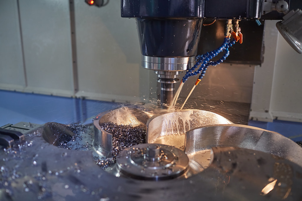
Thread milling uses a rotating multi-tooth cutter that orbits the hole along a helical path on a CNC machining center. It offers several advantages over tapping: a single tool can produce a range of diameters of the same pitch, it works well in hard materials, it allows threading close to the bottom of blind holes, and a broken tool is easy to retract. Thread milling is favored for large-diameter threads, expensive workpieces where scrapping a tapped part is costly, and difficult-to-machine alloys.
Single-Point Threading
On a lathe, single-point threading uses a single cutting tool that makes multiple passes along a rotating workpiece to gradually form the thread. It is the method of choice for external threads on shafts and for large or non-standard pitches. While slower than dies, single-point threading offers excellent control over thread form and is essential for custom or oversized threads.
Thread Inserts (Helicoils and Keylocks)
Thread inserts reinforce or repair internal threads, especially in soft materials such as aluminum and magnesium. A wire-coil insert (commonly known by the Heli-Coil brand) is screwed into an oversized tapped hole to provide a durable, wear-resistant steel thread. Solid bushing inserts such as key-locking inserts offer even higher strength for high-load or repeated-assembly applications. Inserts are also the standard remedy when a tapped hole is stripped, allowing repair without scrapping an expensive part.
Design Rules for Reliable Threads
Good thread design starts on the drawing. The following rules help ensure that a threaded feature is manufacturable, strong, and properly documented.
Thread Engagement and Depth
Thread strength depends on the length of engagement, not on adding more threads indefinitely. A widely used guideline is to engage a length of 1 to 1.5 times the nominal diameter in steel, and 1.5 to 2 times the diameter in softer materials such as aluminum. Beyond roughly two diameters, additional engagement adds little strength because load distributes unevenly across the first few engaged threads. For blind holes, the drilled depth must exceed the threaded depth to leave room for chips and tap runout, and the full-thread depth should be called out explicitly.
Tap Drill Size
The pre-threading hole, or tap drill, determines the percentage of full thread depth. A common target is 70 to 75 percent thread engagement, which captures most of the available strength while keeping tapping torque and tap breakage low. Chasing 100 percent thread engagement dramatically increases torque and tool wear for only a marginal strength gain. For example, an M6 x 1.0 thread typically uses a 5.0 mm tap drill. Forming taps require a larger drill than cutting taps for the same thread because material is displaced rather than removed.
Class of Fit
Class of fit defines the tolerance between mating internal and external threads. In the metric system, internal threads use a number-letter code such as 6H and external threads use 6g, where the number is the tolerance grade and the letter is the position. The 6H/6g combination is the general-purpose standard. In the Unified system, fit is expressed by class number: Class 2A/2B is the general-purpose standard, 1A/1B is loose for quick assembly, and 3A/3B is tight for precision or high-load joints. Internal threads carry the letter B and external threads carry the letter A.
Thread Callouts
A complete callout removes ambiguity for the machinist. A metric internal thread might read M8 x 1.25 - 6H, and an inch thread 1/4-20 UNC-2B. For blind holes, the drawing should state the thread depth and the drill depth separately. Including the standard reference, class of fit, and depth prevents the most common interpretation errors during quoting and production.
Common Pitfalls to Avoid
Many thread problems trace back to a handful of recurring mistakes. Watching for these during design review and supplier communication saves time and cost:
- Mixing incompatible standards. NPT and BSP, or metric and inch, can look similar but never mate correctly. Always confirm the standard on both the part and the mating component.
- Omitting class of fit or thread depth. A callout of just "M8" leaves pitch, tolerance, and depth to interpretation. Specify the full designation.
- Over-specifying engagement. Calling out excessive thread depth raises cost and tap-breakage risk without meaningful strength gains. Match engagement to material and load.
- Threading too close to the bottom of a blind hole. Cutting taps cannot reach the very bottom; allow clearance or use thread milling where full-depth threads are essential.
- Ignoring material behavior. Soft alloys strip easily; specify inserts or adjust engagement length rather than assuming steel-grade performance.
- Forgetting the sealing method on pipe threads. Parallel pipe threads need a face seal; tapered threads need sealant. Confirm which the application requires.
Putting It Together
Threads are deceptively simple features that demand precise specification and the right production method. Selecting the correct standard, calling out the class of fit and thread depth, sizing the tap drill for sensible engagement, and matching the threading method to the material and geometry are the steps that separate a reliable joint from a costly failure. When pipe threads are involved, confirming the sealing mechanism is just as important as the thread form itself.
At MechPart Pro, our ISO 9001 certified facility in Shanghai produces threaded precision components across CNC machining, casting, forging, and more, shipping to customers in over 40 countries. If you are finalizing a design with critical threaded features, our engineering team can review your drawings for manufacturability and recommend the most reliable threading approach for your application. Contact us to discuss your next project.
Related capabilities
Have a part to make?
Upload your CAD for a detailed quote and free DFM feedback within 24 hours.