Sheet Metal Fabrication: Processes, Materials & Design Tips
A practical guide to sheet metal fabrication processes, common materials, and DFM rules for engineers and procurement teams sourcing parts.

Sheet metal fabrication turns flat blanks of metal into functional three-dimensional parts through cutting, forming, and joining. It is one of the most versatile and cost-effective manufacturing methods available to mechanical engineers, particularly for enclosures, brackets, chassis, and structural components produced in low to high volumes. Because tooling costs are modest compared with casting or injection molding, sheet metal is often the fastest route from prototype to production.
This guide walks through the core fabrication processes, the materials engineers reach for most often, and the design-for-manufacturability (DFM) rules that separate a part that ships on time from one that bounces back with quality issues. Whether you are a design engineer finalizing a model or a procurement buyer evaluating suppliers, understanding these fundamentals helps you specify parts that are manufacturable, repeatable, and economical.
The Core Sheet Metal Fabrication Processes
A finished sheet metal part typically moves through three stages: cutting the flat blank, forming it into shape, and joining it to other components. Each stage offers several process options, and the right choice depends on material, thickness, geometry, tolerance, and volume.
Cutting: Laser, Plasma, and Punching
Cutting separates the flat profile from the raw sheet. The three most common methods each have a sweet spot:
- Laser cutting uses a focused beam to vaporize or melt material along a programmed path. It delivers tight tolerances, clean edges, and intricate detail, and is well suited to steel, stainless steel, and aluminum across a wide thickness range. Fiber lasers in particular handle thin-to-medium gauge metals efficiently and excel at complex contours and small holes.
- Plasma cutting uses an ionized gas jet to cut electrically conductive metals. It is faster and more economical than laser on thicker plate, though the kerf is wider and the edge quality is lower, often requiring secondary finishing.
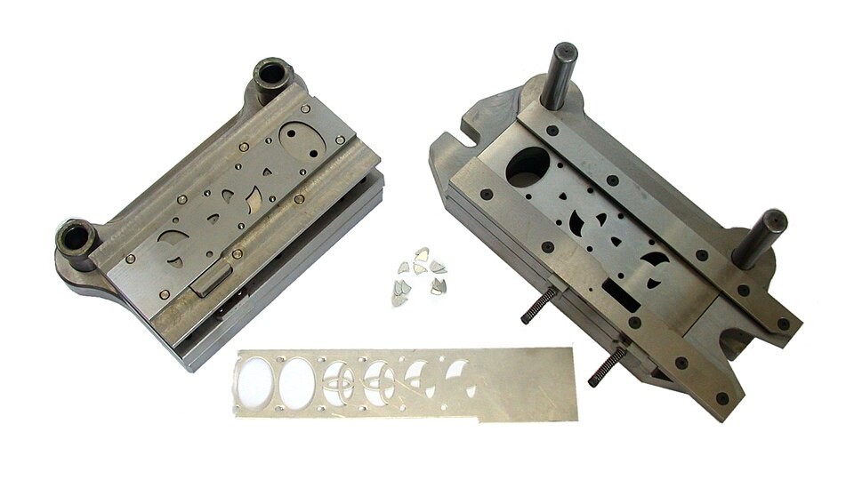
- Punching (turret or CNC punch press) uses hardened tooling to shear holes and shapes out of the sheet. It is highly productive for repetitive features such as hole patterns, louvers, and knockouts, and can also form simple features like dimples and countersinks in the same operation.
Waterjet cutting is a fourth option worth noting: it cuts almost any material without heat, avoiding the heat-affected zone (HAZ) that laser and plasma can introduce, which matters for heat-sensitive alloys.
Bending and Forming: The Press Brake
Once the blank is cut, bending gives it three-dimensional shape. The press brake is the workhorse here, pressing the sheet between a punch and a die to create precise angular bends. Air bending, bottoming, and coining are the common techniques, differing in how far the punch drives the material into the die and how tightly the final angle is controlled.
Beyond simple bends, forming operations such as rolling, stamping, deep drawing, and spinning create curves, channels, embossments, and hollow shapes. The key constraint in all forming is the material's ductility: bend it too tightly and the outer surface cracks; bend it across the grain direction and you improve formability.
Joining: Welding and Mechanical Fasteners
Most assemblies require joining cut and formed parts together. Common options include:
- MIG and TIG welding for strong, permanent metallurgical joints. TIG offers finer control and cleaner welds on thin material and stainless steel, while MIG is faster for thicker sections.
- Spot welding for joining overlapping sheets quickly, widely used in enclosures and chassis.
- Self-clinching hardware such as press-fit nuts, studs, and standoffs that install into punched holes without welding.
- Riveting and threaded fasteners where serviceability or dissimilar-material joints are required.
Welding introduces heat that can distort thin sheet and create a HAZ, so designers should weigh it against mechanical joining, especially on cosmetic surfaces.
Common Sheet Metal Materials
Material selection drives cost, weight, corrosion resistance, and formability. The three families below cover the vast majority of fabricated parts.
| Material | Key Properties | Typical Applications | Considerations |
|---|---|---|---|
| Cold-rolled steel (CRS) | High strength, good formability, low cost, smooth finish | Enclosures, brackets, frames, chassis | Requires painting, plating, or powder coating for corrosion protection |
| Stainless steel (304, 316) | Excellent corrosion resistance, strong, hygienic | Food, medical, marine, outdoor enclosures | Higher cost; springback and tool wear during forming; 316 adds chloride resistance |
| Aluminum (5052, 6061) | Lightweight, corrosion resistant, good conductivity | Electronics housings, heat sinks, aerospace, transport | 5052 bends well; 6061 is stronger but less formable; softer surface marks easily |
| Galvanized steel | Steel with a zinc coating for corrosion resistance | HVAC ducting, outdoor structures, panels | Coating can flake at bends and complicate welding |
| Copper / brass | High electrical and thermal conductivity | Bus bars, electrical contacts, decorative parts | Higher material cost; softer and easily deformed |
For most projects, cold-rolled steel offers the best balance of cost and strength, stainless is chosen when corrosion or hygiene matters, and aluminum wins where weight and conductivity are priorities. Confirming the alloy and temper early prevents downstream surprises in forming and finishing.
Design for Manufacturability (DFM) Rules
Good DFM is where engineering intent meets shop-floor reality. The rules below reduce cost, scrap, and lead time. They are guidelines rather than absolutes, so always confirm specifics with your fabricator, since values shift with material, thickness, and available tooling.
Bend Radius and the K-Factor
Every bend needs a minimum inside radius to avoid cracking or fracturing the outer surface. A common starting point is an inside bend radius equal to at least the material thickness; ductile materials tolerate tighter radii, while harder or thicker stock needs larger ones. Keeping a single, consistent bend radius across a part lets the shop use one tool and improves repeatability.
When a flat sheet bends, the material on the outside stretches and the inside compresses. Somewhere between them lies a neutral axis that neither stretches nor compresses. The K-factor describes where that neutral axis sits, expressed as a fraction of the material thickness, and typically falls between roughly 0.3 and 0.5. Fabricators use it to calculate the bend allowance and produce an accurate flat pattern. If your flat blanks come out the wrong length, the K-factor assumption is usually the culprit.
Bend Relief and Bend Order
When a bend sits near the edge of a feature, the metal can tear or distort. A bend relief is a small slot or notch cut at the end of a bend line to let the material move cleanly. As a rule, make the relief at least as wide as the material thickness and slightly longer than the bend radius. Planning the sequence of bends also matters: a part must be foldable without a flange colliding with the press brake.
Hole and Feature Placement
Holes, slots, and cutouts placed too close to a bend will deform when the metal is formed. The standard guidance:
- Hole-to-bend distance: keep holes at least 2.5 times the material thickness plus the bend radius away from the inside of a bend.
- Hole-to-edge distance: maintain a minimum of about 2 times the material thickness between a hole and the part edge to prevent bulging or tearing.
- Minimum hole diameter: for punched holes, keep the diameter equal to or greater than the material thickness to protect tooling and avoid distortion.
- Feature-to-feature spacing: leave enough web between adjacent holes and slots so the material does not collapse.
Tolerances
Sheet metal is inherently less precise than CNC machining because forming introduces variation. Specifying unnecessarily tight tolerances drives up cost without adding value. The table below offers typical achievable tolerances as a planning reference; your supplier can confirm what is realistic for a given geometry.
| Feature | Typical Tolerance |
|---|---|
| Laser-cut edge to edge | ±0.1 to ±0.2 mm |
| Hole diameter | ±0.1 mm |
| Bend angle | ±1 degree |
| Edge to bend | ±0.2 to ±0.4 mm |
| Across multiple bends (tolerance stack-up) | ±0.4 mm or more |
Apply tight tolerances only to the features that truly need them, such as mating interfaces, and relax everything else. Calling out a datum scheme and identifying critical-to-function dimensions helps the shop prioritize what matters.
Typical Applications
Sheet metal fabrication appears across nearly every industry. Common part categories include:
- Enclosures and housings: electrical cabinets, server racks, control boxes, and consumer-product casings that protect internal components.
- Brackets and mounts: simple formed parts that locate, support, and connect components within a larger assembly.
- Chassis and frames: structural backbones for machinery, appliances, and electronic equipment.
- Panels and covers: access doors, guards, and cosmetic skins.
- Ducting and channels: airflow and cable-management components in HVAC and industrial systems.
Because these parts span a huge range of sizes, finishes, and precision requirements, pairing the right process and material with sound DFM is what keeps quality high and cost predictable.
Bringing It Together
Successful sheet metal fabrication is a conversation between design and manufacturing. Choose the cutting method that fits your material and detail level, design bends and forms within the limits of the alloy, and respect the spacing, relief, and tolerance rules that keep parts producible. Doing so up front avoids costly redesign loops and shortens lead times.
MechPart Pro supports engineers and procurement teams with sheet metal fabrication alongside complementary capabilities including CNC machining, surface treatment, and assembly, all under an ISO 9001 quality system. If you are planning a new part, sharing your drawings or 3D models early for a DFM review is the simplest way to confirm manufacturability before committing to tooling.
Related capabilities
Have a part to make?
Upload your CAD for a detailed quote and free DFM feedback within 24 hours.