Plastic Injection Molding: A Design Guide for Better Parts
A practical design guide to injection molding: resins, wall thickness, draft, ribs, gates, defect fixes, and tooling economics for better parts.

Plastic injection molding is one of the most widely used manufacturing processes for producing precision polymer components at scale. Yet the quality, cost, and manufacturability of a molded part are largely determined long before steel is cut for the mold. They are decided at the design stage. Engineers who understand how molten polymer flows, cools, and shrinks inside a cavity can design parts that fill cleanly, eject reliably, and hold tolerance run after run. This guide walks through the process fundamentals, the most common engineering resins, the core design rules, defect prevention, and the tooling economics that shape every injection molding program.
How Injection Molding Works
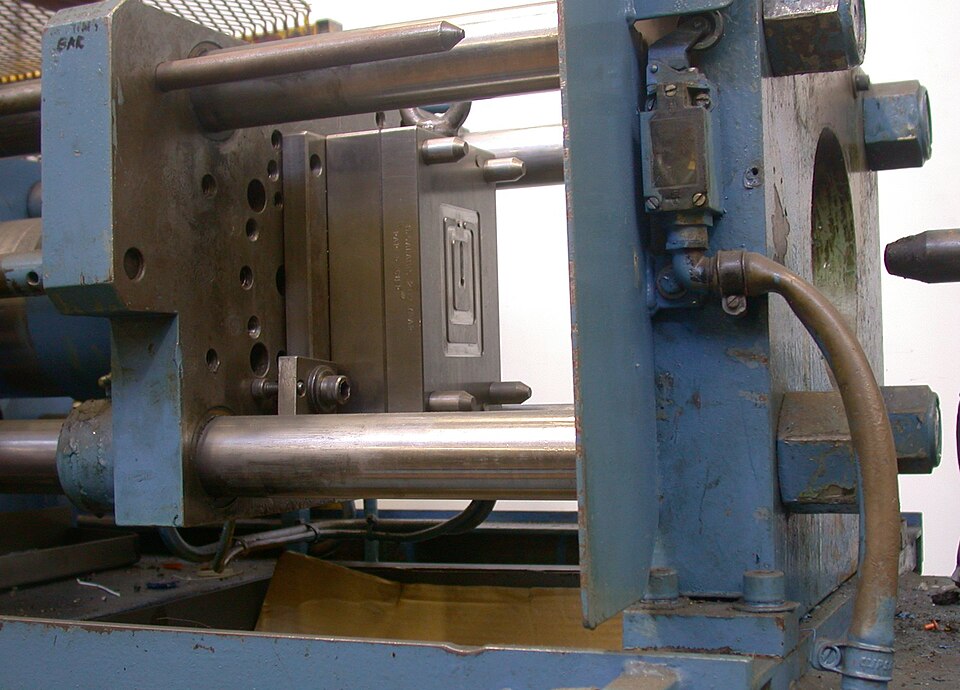
The process is conceptually simple but mechanically demanding. Solid polymer pellets are fed into a heated barrel, where a reciprocating screw melts and homogenizes the material. The molten resin is then injected under high pressure into a closed, temperature-controlled steel mold. Inside the cavity, the polymer cools and solidifies into the shape of the part. The mold opens, ejector pins push the part out, and the cycle repeats. A typical cycle lasts from a few seconds to roughly a minute, depending on wall thickness, material, and part size.
The phase that most influences part quality is the cooling and packing stage. As the polymer cools, it shrinks. The packing pressure applied after the cavity fills compensates for some of this shrinkage, but uneven cooling and uneven wall sections create internal stresses that lead to warping, sink, and dimensional drift. This is why nearly every design rule that follows traces back to one objective: helping the polymer fill and cool as uniformly as possible.
Choosing the Right Resin
Material selection drives mechanical performance, chemical resistance, thermal limits, and cost. Thermoplastics, which can be repeatedly melted and solidified, dominate injection molding. The table below summarizes commonly specified engineering resins and their typical applications.
| Resin | Key Characteristics | Typical Applications |
|---|---|---|
| ABS | Tough, rigid, good surface finish, easy to machine and paint; moderate heat resistance | Housings, enclosures, consumer products, automotive trim |
| PC (Polycarbonate) | High impact strength, optical clarity, good heat resistance; notch-sensitive | Lenses, safety guards, electrical components, transparent covers |
| PA (Nylon) | Strong, wear-resistant, good chemical resistance; absorbs moisture | Gears, bearings, structural brackets, under-hood parts |
| POM (Acetal) | Low friction, high stiffness, dimensional stability, good fatigue resistance | Gears, bushings, snap fits, precision mechanical parts |
| PP (Polypropylene) | Low cost, chemical and fatigue resistant, good living-hinge performance; lower stiffness | Closures, living hinges, containers, automotive interiors |
| PEEK | Exceptional thermal, chemical, and mechanical performance; high cost | Aerospace, medical, semiconductor, demanding high-temperature parts |
Glass-fiber or mineral fillers can be added to most of these resins to increase stiffness, strength, and dimensional stability, though they raise tool wear and can alter shrinkage behavior. Always confirm the grade-specific datasheet values for shrinkage, melt temperature, and recommended draft, because properties vary significantly between grades of the same base polymer.
Core Design Rules for Moldability
Uniform Wall Thickness
Uniform wall thickness is the single most important design principle in injection molding. Because plastic shrinks as it cools, thick sections cool more slowly than thin ones, creating differential shrinkage that drives warpage and sink marks. As a rule of thumb, walls should be kept as uniform as possible, with most engineering thermoplastics falling between roughly 1 mm and 4 mm. Where a transition between thicknesses is unavoidable, blend it gradually rather than with an abrupt step, ideally over a distance of about three times the wall thickness.
Draft Angles
Draft is the slight taper applied to walls that run parallel to the direction of mold opening, allowing the part to release cleanly from the cavity. Without draft, parts drag against the steel, scuff, or stick. A common starting point is at least 1 degree of draft per side, with 1.5 to 2 degrees preferred for deeper walls. Textured surfaces require additional draft, often 1 degree per 0.025 mm of texture depth, because the texture increases friction during ejection.
Ribs and Bosses
Ribs add stiffness without increasing wall thickness, which would otherwise invite sink and warp. To avoid sink marks on the opposite face, rib thickness at the base should generally be limited to 40 to 60 percent of the adjoining wall thickness. Rib height is typically kept to no more than about three times the wall thickness, and each rib should include draft and a small radius at its base. Bosses, the cylindrical features that receive screws or pins, should be supported by gussets or ribs rather than thickened, and connected to walls with thin ribs rather than solid masses of material that would trap heat and shrink unevenly.
Gate and Parting Line Placement
The gate is the point where molten plastic enters the cavity, and the parting line is where the two mold halves meet. Both have visible and structural consequences. Gates should be positioned to fill the part from thick to thin sections, promote even flow, and minimize the distance the melt must travel. Their location also dictates where weld lines and cosmetic vestiges appear, so gates are best placed on non-cosmetic surfaces. The parting line should be planned early, as it influences draft direction, flash location, and tooling complexity. Coordinating these decisions with your manufacturing partner during design review prevents costly tool revisions later.
Radii and Corners
Sharp internal corners concentrate stress and disrupt material flow, weakening the part and creating fill problems. Generous radii distribute stress, improve flow, and extend mold life. A common guideline is an internal radius of at least 0.5 times the wall thickness, with the corresponding outer radius equal to the inner radius plus the wall thickness, which helps preserve uniform wall section through the corner.
Common Defects and How to Fix Them
Most molding defects stem from the interaction of part geometry, material behavior, and process parameters. The most effective fixes address the root cause in the design, with process tuning as a secondary lever. The table below maps frequent defects to their typical causes and corrective actions.
| Defect | Typical Cause | Design and Process Fixes |
|---|---|---|
| Sink marks | Thick sections or ribs cooling slower than surrounding wall; insufficient packing | Reduce local thickness, core out heavy sections, limit rib base thickness, increase packing pressure and time |
| Warpage | Differential shrinkage from non-uniform walls or uneven cooling | Uniform wall thickness, balanced cooling layout, optimized gate location, fiber orientation review |
| Flash | Material escaping the parting line due to excessive pressure or poor clamp/tool fit | Reduce injection pressure, increase clamp tonnage, maintain and reseat mold faces, check parting-line venting |
| Weld lines | Two flow fronts meeting after splitting around a hole or core, leaving a weak seam | Relocate gate, raise melt and mold temperature, add flow leaders, reposition holes away from load paths |
| Short shots | Cavity not fully filling due to thin walls, trapped air, or low pressure | Increase wall thickness or pressure, add venting, shorten flow length, raise melt temperature |
Modern mold-flow simulation can predict fill patterns, weld-line positions, and warpage before a mold is cut, making it a valuable step for complex or high-volume parts. Running simulation during the design phase is far cheaper than discovering problems in hardened steel.
Tooling and Volume Economics
The defining economic feature of injection molding is its cost structure. A steel mold represents a significant upfront investment, but once built, the per-part cost is very low. This makes the process highly sensitive to production volume. The tooling cost is amortized across every part produced, so the more parts a program runs, the lower the effective cost per piece.
Several factors drive tooling cost and the volume threshold at which molding becomes economical:
- Mold material: Aluminum or soft-steel tools are cheaper and faster to build, suiting prototypes and lower volumes, while hardened steel tools cost more but last for hundreds of thousands to millions of cycles.
- Cavitation: A multi-cavity mold produces several parts per cycle, raising tool cost but dramatically lowering per-part cost at high volumes.
- Part complexity: Undercuts, side actions, and tight tolerances add to mold design, machining, and maintenance costs.
- Surface finish and texture: Polished optical finishes or specified textures require additional tooling labor.
For low volumes or early validation, processes such as CNC machining or additive manufacturing often deliver parts faster and without tooling investment. As annual volumes climb into the thousands and beyond, injection molding usually becomes the lowest-cost option. Mapping expected lifetime volume against tooling strategy early in a project is one of the most consequential decisions a procurement team can make.
Designing for Success from the Start
Injection molding rewards discipline at the design stage. Uniform walls, adequate draft, well-proportioned ribs and bosses, thoughtful gate and parting-line placement, and generous radii together eliminate the majority of defects before they occur. Pairing sound design with the right resin and a tooling strategy matched to volume produces parts that are stronger, more consistent, and less expensive over the life of the program.
At MechPart Pro, our engineering team supports design-for-manufacturability reviews across injection molding and complementary processes including CNC machining, casting, forging, sheet metal, and additive manufacturing. If you are weighing material choices, tooling strategy, or moldability on an upcoming program, our engineers are available to review your design and recommend a practical path to production.
Related capabilities
Have a part to make?
Upload your CAD for a detailed quote and free DFM feedback within 24 hours.